Support on this page via E-Mail...
This chapter deals with basic functions in DDS-CAD. Model handling, project, screen, menus, help geometry handling, project, screen, menus, help geometry.
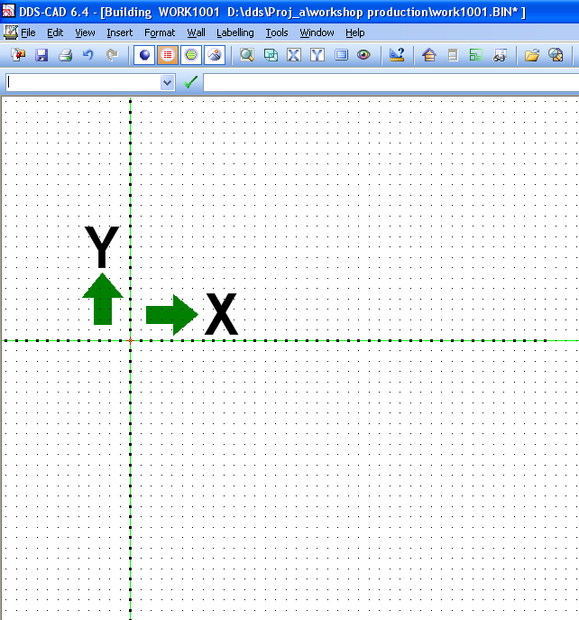
We presume that a new project has been created, and you are ready for drawing tasks. The screen can be compared with a sheet where you use ruler, pencil and paper. On the screen you can see a small cross indicating the last entered point/position. When you start a new drawing, the small cross is positioned in the origin of the three dimensional co-ordinate system (X = 0, Y = 0, Z = 0). If a grid (”module net”) is active, the X and Y axis is clearly indicated through the origin in the drawing.
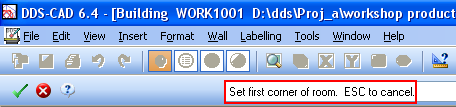
At the top of the screen you will see the version number (6.40), the name of the current drawing and the folder (directory) in which it has been saved. The next line is the pull down menu, where a number of sub menus can be activated. Select in the menu by pointing on the required option and press the left mouse button.
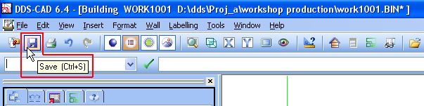
At the top you find the main button row, and several of the buttons can also correspond with menu commands. You will see the function of the various buttons by resting the cursor on a button. A box with explaining text will appear – screen tips.
If you move a window to another position on screen, it becomes easier to see more than one window at the time, or to see items the window might be hiding. If you move a window, drag the title line to a new position. Point in the title line with the cursor and hold down the left mouse button when dragging the window to a new position.
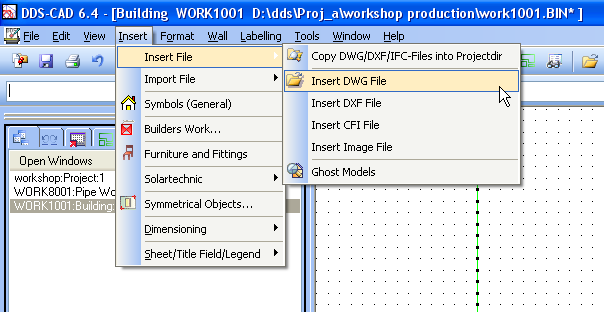
A new window with the same contents is created via the Windows menu. A new window with different contents, i.e. another drawing, can be opened via the File menu or the Project menu. This is in accordance with general Windows standard.
Beneath the toolbar you find the message line. Here commands can be entered directly from the keyboard. Several users want to give orders directly from the keyboard instead of selecting in menus and toolbars – in order to save time.
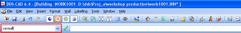
The field to the right displays all messages coming from the program. This can be messages to you about what is to be done, and error messages from the program if something is not like it should be.
The commands – entered from the keyboard are temporarily saved in a list in the message field. These can be reactivated by pointing at the current command in the list, make possible parameter changes and then pressing the button to the left.
When a command is activated either from the command line, the menu or via a button on the toolbar, the reactions will differ, depending on the type of command.
These have in common that the key word for the entered command is displayed – and buttons for:
 Execute = [Line shift] or [Close] or [OK] in the dialog box
 Cancel = [Esc] or [End] in the dialog box
 Help = [Help] in the dialog box
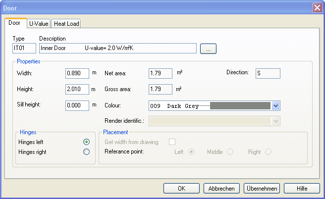
The command entered in the command field together with one or several parameters is executed when you click the Execute button. A number of commands, either selected from the keyboard or entered via menus and toolbars, are activated via dialog boxes in which you have to give answers.
The parameters are entered in the dialog box, and you confirm with [OK]. Example...
Some commands give a message to the user of what is expected to be done on screen. These messages will appear in the message field. Follow the instructions and execute as described – or end with [Esc], [Cancel] or [Stop].
The area on screen displaying your DDS-CAD can be split into several windows. This can be windows displaying different presentations of your model. Besides the drawing area, the screen can be divided into fields used for the line-up of various “content lists”. This could be the contents of the command field (drawing) – i.e. the command list also activated via the command Quick Edit (QE), existing drawings belonging to the project, etc...
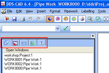
 Open Windows
 Cancel/undo – displays the commands as they have been executed and entered into the list. Here you can cancel/undo (i.e. remove) entered commands. The list is emptied every time you end the drawing, and you can start again to build up a new command list.
 Contents of a command file - Quick Edit - QE
 Room list – provided that you have either defined a room (chapter 6 Room database) or imported an IFC file (chapter 5 IFC Import/Export). For information on how to produce list field and change between the various flags, see the next video clip.
Indicate what is to be handled in the list field with the left mouse button. Click the right mouse button, and the appurtenant context menu is activated. Select:.

| A method for selecting which windows to be displayed, can be done in the list field when the flag Open windows is active. Indicate which windows to be displayed horizontally or vertically. This is done in the Windows manner by means of the [Shift]- or [Ctrl]-key. Click the right mouse button and indicate how the windows are to be displayed |
The list field is usually positioned to the left on screen. The width can be adjusted by positioning the cursor on the list dividing the list field and drawing field. Hold down the left mouse button and drag in the required direction to adjust the width.
The field can also be moved on screen by positioning the cursor in the upper part of the field and holding down the left mouse button while moving. Let go of the mouse button when you have got the correct position.
Turn the list field on/off via the menu Display ® Display vertical field.
You can also select a horizontal list field, but this is not actively used in this version.
This is used to roughly set which modules (tools) in the program you want to work with.

These buttons are static – i.e. it is always the same buttons that are displayed, no matter which tools you have selected. The various toolboxes (white background) decide the tool contents.
This is activated from Display -> Display context menu (also with Ctrl + U). These buttons are mainly used to get the various components in your project.
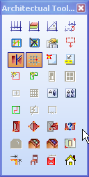
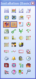
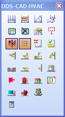
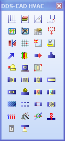
The above images display the tool boxes for Plan Drawing, Electrical Installation and HVAC Installation
When a command has been selected, there are a number of options for this. (If, for instance, you have got a certain component, you have a number of options; positioning, scaling, rotating, characteristics...). You will find these options in the co-called pop-up menus, activated by pressing the right mouse button.
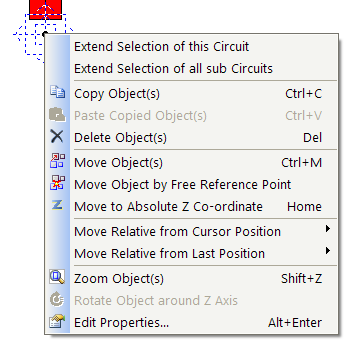
[shift-key] makes all points available
[ctrl-key] makes all lines available
[alt-key] releases all snaps
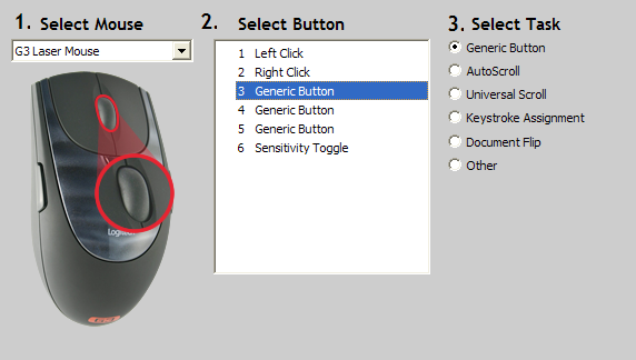
In this documentation you are supposed to have a three-button mouse, and that you are right-handed. If you are left-handed, you can change the left and right button. We recommend a mouse with roll-button in the middle – as this button can both be rolled and pressed. Both functions are used in this program.
Check in the Control panel and Characteristics for the mouse that the middle mouse button has the function ”Middle button” active. This will not influence on the roll function in other programs.
Check in the Control panel and Characteristics for the mouse that the middle mouse button has the function ”Middle button” active. This will not influence on the roll function in other programs.
DDS-CAD has, besides using the mouse as a pointing unit for marking elements on screen, added other useful functions to the three buttons. This will increase the efficiency when using the options in the program.
Left mouse button = mark element, select in the menu or enter position – see also chapter 3
Middle mouse button = examine the drawing/zoom – see also chapter 2
Right mouse button = display context menu/pop-up menu
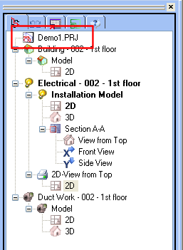
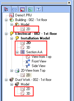
The Docking Panel displays a tree structure showing the hierarchy of the currently open data objects (models, drawings, sections, views etc...).
|
Important Changes to a printing layout in the DDS Explorer does not update its contents. In order to update the printing layout, you use the function " File->Show Plot Assembly" menu command. |

Docking Panel - DDS Explorer
Overview of DDS Explorer Contents
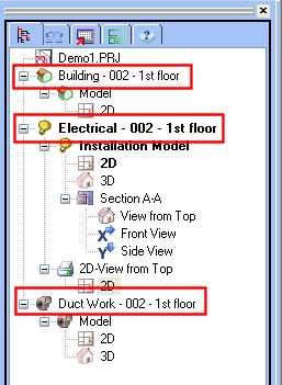
Project
DDS Explorer - Project
The project is the external repository for all the data of a building project. Under the aspect of the project management a project consists of several drawings, which - depending upon discipline - represent either a floor or a distribution board or a system. The structure of the project is controlled via the Drawing List.
Drawing
DDS Explorer - Drawing
A drawing is in each case a file, which carries the ending *.BIN. It is created by application of the Drawing List and is provided automatically with a file name. It contains either a floor of the building or a system of the technical installation. The internal structure of a drawing is structured into models, presentations and views. It is displayed in the DDS Explorer.
Models
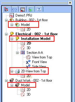
DDS Explorer - Models
Each drawing can consist of several work areas, which are called models. In the DDS Explorer they appear below each drawing. There are basically two types of models, work models and print layouts.
The work model is the place for the planning of the building or the technical system. All representations take place in the original scale, i.e. on a scale 1: 1. Depending upon discipline and installation type the following work is executed:
The work model can be presented in different form (2D; 3D; Window).
The printing layout is the area, where sections of the work model are prepared to the formalised output required. The following work is executed:
The printing layout can contain only in each case one presentation with in each case a page.
Presentation
DDS Explorer - Presentation
< Previous Section - Next Section >
